Controlling DC motors is an essential aspect of robotics and automation projects. The L293D Motor Driver Board is a popular choice for driving motors efficiently using microcontrollers like Arduino and Raspberry Pi. This guide will walk you through the step-by-step process of setting up and using the L293D motor driver to control DC motors.
What is L293D Motor Driver Board?
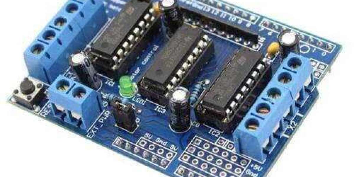
The L293D is an H-Bridge motor driver IC that allows bidirectional control of DC motors. It can control up to two motors simultaneously and supports PWM (Pulse Width Modulation) for speed control. The L293D can handle motors operating at 4.5V to 36V with a peak current of 600mA per channel.
Features of L293D Motor Driver:
Can drive two DC motors independently.
Dual H-Bridge for bidirectional motor control.
PWM support for speed control.
Built-in flyback diodes for protection against back EMF.
Compatible with Arduino, Raspberry Pi, and other microcontrollers.
Components Required
Before we start, gather the following components:
L293D Motor Driver Board
Arduino Uno (or any other microcontroller)
Two DC motors
Power source (Battery pack or 12V adapter)
Jumper wires
Breadboard (optional)
Pin Configuration of L293D
The L293D has 16 pins, which include control, power, and motor output pins:
Vcc1 (Pin 16) – Logic power supply (5V from Arduino)
Vcc2 (Pin 8) – Motor power supply (4.5V to 36V)
GND (Pins 4, 5, 12, 13) – Ground
Enable1 (Pin 1) – Enables Motor A
Enable2 (Pin 9) – Enables Motor B
Input1 (Pin 2), Input2 (Pin 7) – Controls Motor A
Input3 (Pin 10), Input4 (Pin 15) – Controls Motor B
Output1 (Pin 3), Output2 (Pin 6) – Motor A terminals
Output3 (Pin 11), Output4 (Pin 14) – Motor B terminals
Wiring the L293D with Arduino
Follow these steps to connect the L293D Motor Driver with an Arduino Uno and two DC motors:
Step 1: Power Connections
Connect Vcc1 (Pin 16) to 5V on the Arduino.
Connect Vcc2 (Pin 8) to the motor power supply (e.g., 12V battery pack).
Connect all GND pins (4, 5, 12, 13) to GND on the Arduino.
Step 2: Motor Connections
Connect Motor A to Output1 (Pin 3) and Output2 (Pin 6).
Connect Motor B to Output3 (Pin 11) and Output4 (Pin 14).
Step 3: Control Pin Connections
Connect Enable1 (Pin 1) to Arduino Digital Pin 9 (PWM-enabled).
Connect Enable2 (Pin 9) to Arduino Digital Pin 10 (PWM-enabled).
Connect Input1 (Pin 2) to Arduino Digital Pin 2.
Connect Input2 (Pin 7) to Arduino Digital Pin 3.
Connect Input3 (Pin 10) to Arduino Digital Pin 4.
Connect Input4 (Pin 15) to Arduino Digital Pin 5.
How the Code Works
Define Pin Assignments: We assign Arduino pins to the L293D motor driver.
Setup Function: All motor control pins are set as OUTPUT.
Loop Function:
Motors move forward for 2 seconds.
Motors move backward for 2 seconds.
Motors stop for 2 seconds before repeating.
Applications of L293D Motor Driver
Robotics Projects: Line-following robots, obstacle-avoidance robots.
Automated Vehicles: RC cars, autonomous rovers.
Home Automation: Automated door systems, conveyor belts.
IoT Projects: Motorized smart devices.
Conclusion
The L293D Motor Driver Board is a versatile and reliable component for controlling DC motors in various electronic projects. By following this guide, you can easily set up and program your L293D with Arduino to control motor movements efficiently. Whether you're working on a robotics project or an automation system, mastering this motor driver will be a valuable skill!
For purchasing the L293D Motor Driver Board, visit Campus Component.